
A progressive die that stamps good panels at the start of a shift can drift, and visual inspection can miss it. If this is not corrected, it will produce product that is out of tolerance and must be discarded. An eddy current displacement sensor measures the distance to a steel or aluminium surface without contact, through the oil film and mist around a press. Its fast measurement speed gives a reading on every stroke. It can be mounted in or around the die to produce a live signal trend, so the drift shows as a slope on a chart while the parts are still in tolerance.
Why first-off inspection is not sufficient to catch drift
Tolerance drift on a press builds over hundreds of strokes. When the die and the press frame heat up, the thermal growth changes the shut height and subsequently it changes the clearance between punch and die. Drift may also be caused by tool wear on the working surface, which changes the radii the sheet forms over and the clearance it is drawn through. Both causes alter springback, and a few tenths of a millimetre of change is enough to move a flange or a hole position out of a tight automotive tolerance.
Traditionally, a first-off part is checked on a coordinate measuring machine (CMM) and then sampled every hour or every few hundred strokes. Although a CMM check is thorough, each one takes time and describes parts that have already been stamped. It is therefore not suited to continuous operation. As the line keeps running between samples, drift that happens soon after the first sample goes undetected. As a result, several hundred panels can be stamped before the next sample. It is then impossible to tell when the error was first made, and all the products manufactured during this period would be unusable.
The underlying issue with a manual method is the gap between samples. Finding where the error was first made requires continuous measurement. The measurement system used for this application must also withstand the press environment.
How an eddy current sensor measures distance to a metal target
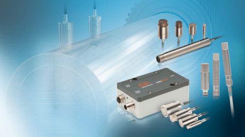
An eddy current sensor has a coil in the tip of the probe. The controller drives that coil with a high-frequency alternating current, which creates an alternating magnetic field in front of the probe. When a conductive target such as a steel panel or a die surface sits inside that field, the field induces small circulating currents in the target. These eddy currents create their own magnetic field, which opposes the field from the coil. The strength of that opposition depends on the distance between the probe and the target, so the coil’s electrical behaviour changes with distance. The controller measures that change and outputs a signal proportional to the distance.
An eddy current sensor only responds to conductive material, so oil, drawing compound, dust and mist in the gap between probe and target do not register. This allows its use in dusty and dirty environments. Measuring ranges are short, from under a millimetre to 80 mm depending on the sensor, so the probe must sit close to the target and is best suited to resolving small changes in distance. Industrial eddy current sensors carry IP67 housings and are rated for ambient temperatures up to 200 °C. The temperature stability of the measuring system is specified so that the shift-long warm-up of the tool does not read as a change in distance.
Using eddy current sensors for die press measurements
Eddy current sensors can be used to measure die closure. Probes mounted at the corners of the die set read the distance to a plate on the opposing half. They show the shut height and the parallelism of the closed die on every stroke. A gradual reduction in shut height at one corner shows thermal growth or wear.
They can also measure panel position after forming. A probe reads the distance from a fixed point on the lower tool to the surface of the formed panel. Once the punch has lifted, it measures how far the panel has sprung back. That distance is the springback, and the sensor allows it to be tracked stroke by stroke. A slow rise in the reading is the trend the operator needs to see.
At the blank holder, a third probe can read where the sheet is clamped against the die surface. Measuring the sheet’s position against the known die surface gives its thickness at that point. An incoming coil with a thickness change at the edge of the material specification shows up here before it changes the formed part.
The user can turn the distance reading into a dimensional measurement and compare it against a reference dimension set once during commissioning. They can then set tolerance limits on the controller’s switching outputs, so an alarm alerts the operator when a reading approaches a tolerance limit. The sensor can also provide analogue or fieldbus output to the process control system or a data acquisition system.
Getting the setup right for an eddy current sensor
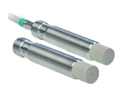
It is essential to understand the target material being measured. Eddy currents behave differently in ferromagnetic steel and in non-ferromagnetic aluminium, so the sensor is linearised for the material it will measure. A three-point linearisation carried out on a sample of the actual sheet or die material sets the calibration. The target must also be large enough to fill the probe’s measuring field and flat enough that the probe sees a consistent surface. The minimum target size can be found on the manufacturer’s datasheet for each probe.
An eddy current sensor must be mounted on a fixed bracket, out of the contact path. A probe that moves with the press frame measures its own movement, and a probe in the path of the tool or the blank will be struck and damaged. A short measuring range means a small standoff distance. Set the bracket so the probe sits at the middle of its range against the reference master. This leaves margin at both ends for the movement being measured.
Choosing an eddy current displacement sensor for a press line
Does a coating or a lubricant on the panel affect the reading?
No. The sensor measures to the conductive metal beneath. Paint, e-coat, oil and drawing compound are not conductive, so the probe reads the metal surface under them. It also means an eddy current sensor cannot measure the thickness of a non-conductive coating on the panel. An optical sensor would be suitable for this type of application.
When is an eddy current sensor the wrong choice?
Measurement on a non-metallic target, such as a plastic trim part or a composite panel, is the main case. A laser triangulation sensor is well suited to those surfaces. Another case is an application that requires a large standoff distance, where the probe cannot sit within a few tens of millimetres of the target. Where the requirement is nanometre resolution on a clean, stable setup, a capacitive sensor is the usual choice.
Can we assist with your in-die measurement application?
Eddy current sensors are typically selected for small distance measurements on conductive material in industrial environments, such as die press and sheet forming applications.
If you are looking at a challenging industrial distance measurement, have a chat with us about your application. Our applications engineers can help you define the project scope, select the equipment and assist with system integration and technical support.
Get non-contact distance measurement on your press line
Tell us three details. We will recommend an eddy current sensor that suits your press.
Target material
Steel, aluminium or another metal
Standoff
Distance from probe to target
Output
Analogue, switching or fieldbus
Or call 03 9540 5100 or email enquiry@bestech.com.au
