
Manufacturing process of flat sheet products such as plasterboard involves operations over long forming line that move at a set speed. As part of quality control, the thickness deviation of the sheets must sit inside a tolerance set by customers as it will decide whether it will fit for purpose.
Non-contact displacement sensors can measure that thickness while the board moves. This is done by positioning two laser triangulation sensors to face each other across the line, one above the board and one below it, and each measures the distance to the surface nearest to it.
The board thickness is the fixed gap between the two sensors minus the two distances. Its non-contact method allows for high-speed measurement without wear, and the result feeds straight into the plant’s control system at the sensor’s measuring rate.
Current technology used for board thickness measurement
Many production lines still incorporate manual thickness measurement as part of their QC. An operator pulls a sample at intervals, measures it with a calliper or a thickness gauge at a few points, and writes the result down or types it into a log. Between each sampling periods, the line keeps running as is.
That measurement method has three weaknesses.
Firstly, thickness drift on a continuous line is usually gradual, caused by a change in slurry density, a forming roller setting or a wear pattern on a roller. A spot check catches the drift only when a sample happens to fall outside tolerance, by which time everything produced since the last check is already a defective product.
Secondly, A handful of readings per shift cannot be lined up against the upstream process settings that were measured live when each metre of board was formed, so the cause of a drift cannot be traced.
Finally, during the sampling process, a contact thickness gauge pressed onto a freshly formed board can mark the liner or compress the core, so the reading is taken on material that is no longer in its as-made condition.
Implementing a continuous, non-contact measurement sensors would addresses all three challenges. It reads every metre rather than a sample. The measurement data it produces is time-stamped and can be laid alongside the process data. Also, no contact wear between the board and the sensors.
How a laser triangulation sensor measures distance
A laser triangulation sensor projects a small laser spot onto the target surface. The light scatters from the surface, and a receiving lens in the sensor focuses part of that scattered light onto a detector array.
Because the laser and the receiver sit at a known angle to each other, the position of the spot on the detector shifts as the target moves closer or further away. The sensor electronics convert that spot position into a distance. The whole measurement happens inside the sensor housing with no moving parts.
In real industrial measurement, the board moves through the production line and exposed to different light intensity depending on the position and the different time of the day. As laser triangulation sensor heavily relies on the light intensity captured by the detector, the sensing element must be able to adjust and compensate for the light intensity as it takes the measurement.
This surface compensation feature from the sensor allows it to adjust its exposure in real time so the detector receives a usable amount of light from a light paper liner, a darker patch or a damp area alike.
In addition, the ambient light environment also may play a factor in the reading. Therefore, the sensors used for measurement must be specified to hold their reading under strong illumination. For example, the optoNCDT 1900, is rated to 50 000 lux.
Why thickness measurement needs two sensors
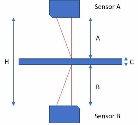
A single sensor mounted above the line measures the distance from itself to the top surface of the board. That number only equals thickness if the underside of the board rests on a fixed, flat reference at a known height, and a moving board on rollers or a belt does not. As the board lifts, sags and flutters between supports which may happen due to movement and vibration, every millimetre of that movement appears as a thickness change that is not real.
The two-sensors arrangement removes the problem. Sensor A can be mounted above the production line and sensor B are mounted below the board. Both sensors are mounted on a rigid frame so the distance between them, H, is fixed. Each measures the distance to the nearest surface of the board.
The thickness C is then C = H − (A + B). If the board lifts by a millimetre, A shrinks by a millimetre and B grows by a millimetre, and C is unchanged.
Two conditions must exist to make this measurement possible. The sensors must be aligned on the same measurement axis, so both measurement spots sit on the same point of the board from opposite sides.
The reading must also be time-synchronised, so both readings are taken at the same instant. This is because on a fast-moving line, a delay between the two sensors means measurement are conducted on different parts of the board and the calculated thickness is wrong.
A two-sensor frames can be used to mitigate this mounting problem. Micro Epsilon has developed the thicknessSENSOR, which is a system that mounts two laser triangulation sensors on a rigid C-frame so the alignment and spacing are set before the unit reaches the line.
The value of H is fixed by measuring a reference piece of known thickness once the frame is in position, and the same reference is used to check the system at intervals.

How to get the right measurement on the line
The measuring rate must match the line moving speed. If you divide the line speed by the sensor’s measuring rate, you have the distance between readings along the board.
At 1 kHz, a line moving at 1 m/s gives one reading every millimetre; at 10 kHz, one reading every 0.1 mm. Most thickness measurement needs far less measurement points than that, so the additional data can be averaged to produce steady reading over a textured surface.
The measuring range is set by the board’s movement as well as by its thickness. If the board can flutter 5 mm between supports, each sensor needs a range that holds the surface within its measuring window through that movement, with margin at both ends. A 10 mm to 50 mm range suits most production lines, since the start of range sets the clearance to the board.
The choice of the output signals depends on the control system. An analogue 4 to 20 mA output into a PLC input is the simplest route where the plant only needs the thickness value.
When the readings are to be logged at full rate or combined measurement from several sensors are needed, Digital signals such as RS422, Ethernet or EtherCAT output can be used as it carries the data without the resolution loss of an analogue channel.
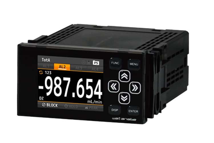
To produce thickness value that can be visible for an operator on the floor, a graphical digital panel meter such can take both sensor inputs, calculate C = H − (A + B) on board, display the thickness at the line. It can also be configured with switch and relay output to raise an alarm when the thickness measured are outside the tolerance.
Thickness measurement is usually not the only dimension plasterboard plant wants from the same measurement system. For example, edge angle and groove profile on board can provide information on the sheets fit together. For this type of multi-dimensional position measurement, a laser line profile sensor mounted at the edge measures the full cross-section so those properties can be calculated automatically alongside the thickness.
Products for inline board measurement
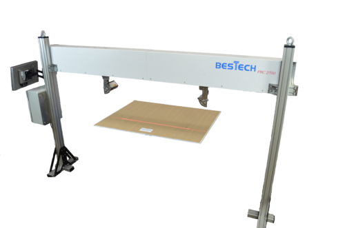
See it in practice: inline automated thickness measurement on plasterboard
How do you specify the right non-contact displacement sensor for your application?
If you are looking at inline thickness, position or dimension measurement on a moving product, have a chat with us about your application as the specifying work can often be complex and choosing the wrong systems would be detrimental for your plant.
Our applications engineers can help you define the project scope, select the equipment and assist with system integration and technical support.
